3 The Nonlinear Pendulum
Learning Objectives
At the end of this chapter, you will be able to do the following.
- Apply the modeling process to a simple mechanical system, the nonlinear pendulum.
- Use Newton’s law to derive a differential equation for the dynamics of the pendulum.
- Combine variables and parameters into dimensionless quantities.
- Assess whether a mathematical model is dimensionally correct.
- Synthesize the dynamics of an autonomous second order differential equation by means of energy methods or phase plane analysis.
Nature of the problem, assumptions and model equations
We consider the motion of a pendulum, that is of a mass suspended at one end of a string, the other end being attached to a fixed point (see Figure 3.1). It is known that the period of the pendulum depends on its amplitude. We refer the reader to Figure 4 of a 2005 article by Lima and Arun, and references therein.
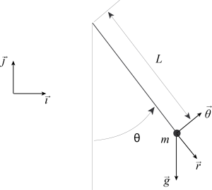
In what follows, we will assume that the object attached to the string is a point mass, that the string is massless and that neither the mass of the object nor the length of the string change with time. We will consider that motion takes place in a plane (note this is an approximation since the pendulum tends to undergo a slow precession motion). We will use Newton's law to describe the dynamics of the pendulum. The forces acting on the mass are the force of gravity [latex]\vec F_g[/latex], which we will consider constant (see exercises for a justification), the tension [latex]\vec F_t[/latex] exerted by the string, and the friction force [latex]\vec F_f[/latex] exerted on the mass by the surrounding air. We will assume that this force is proportional to the negative of the velocity of the mass. This too is an approximation; for more information, see for instance Pendulum Damping by P. Squire (1986).
In order to set up the problem, we define a basis of vectors [latex](\vec \imath, \vec \jmath)[/latex] for the plane in which the motion is taking place. We call [latex]l[/latex] the length of the string and [latex]m[/latex] the mass of the object attached to the string. We measure the position of the point mass in terms of the angle [latex]\theta[/latex] between the string and the vertical (see Figure 3.1). The position vector of the point mass [latex]\vec x[/latex] is given by
[latex]\vec x = l \sin(\theta)\, \vec \imath - l \cos(\theta)\, \vec \jmath \equiv l \vec r,[/latex]
where [latex]\vec r = \sin(\theta) \vec \imath- \cos(\theta) \vec \jmath[/latex]. The unit vector orthogonal to [latex]\vec r[/latex] and such that [latex](\vec r, \vec \theta)[/latex] forms a direct basis of the [latex](x,y)[/latex] plane is [latex]\vec \theta = \cos(\theta)\, \vec \imath+ \sin(\theta)\, \vec \jmath.[/latex]
We can now use this information to express the first and second derivatives of the position vector [latex]\vec x[/latex] in terms of the vectors [latex]\vec r[/latex] and [latex]\vec \theta[/latex], as well as of the derivatives of the angle [latex]\theta[/latex]. Indeed, we have
[latex]\displaystyle \frac{d \vec x}{d t} = \left(l \cos(\theta)\, \vec \imath+ l \sin(\theta)\, \vec \jmath\,\right) \frac{d \theta}{d t} = l \frac{d \theta}{d t} \vec \theta \qquad (3.1)[/latex]
[latex]\begin{align} \frac{d^2 \vec x}{d t^2} &= l \frac{d^2 \theta}{d t^2} \vec \theta + \left(- l \sin(\theta)\, \vec \imath+ l \cos(\theta)\, \vec \jmath\,\right) \left(\frac{d \theta}{d t}\right)^2 \\ & = l \frac{d^2 \theta}{d t^2} \vec \theta - l \left(\frac{d \theta}{d t} \right)^2 \vec r. \end{align} \qquad (3.2)[/latex]
Newton's law tells us that the acceleration of the point mass is equal to the sum of the forces applied to the mass. In other words, we have
[latex]\displaystyle m \frac{d^2 \vec x}{d t^2} = \vec F_g +\vec F_t +\vec F_f, \qquad (3.3)[/latex]
where
- [latex]\vec F_g = - m g \, \vec \jmath= m g \cos(\theta)\, \vec r - m g \sin(\theta)\, \vec \theta[/latex] is the force of gravity,
- [latex]\vec F_t = - T\, \vec r[/latex] is the tension exerted by the string,
- [latex]\displaystyle \vec F_f = - c \frac{d \vec x}{d t} = - c l \frac{d \theta}{d t}\, \vec \theta[/latex], with [latex]c \gt 0[/latex], is the friction force (we used Equation (3.1) to obtain the last equality).
Note that we have expressed the forces in terms of the vectors [latex]\vec r[/latex] and [latex]\vec \theta[/latex], and not [latex]\vec \imath[/latex] and [latex]\vec \jmath[/latex]. The reason is that the expression for [latex]d^2 \vec x / d t^2[/latex] is simple if written in terms of [latex]\vec r[/latex] and [latex]\vec \theta[/latex] (see Equation (3.2)). Putting all of this information together, we obtain
[latex]\displaystyle m l \frac{d^2 \theta}{d t^2} \, \vec \theta - m l \left(\frac{d \theta}{d t}\right)^2 \, \vec r = m g \cos(\theta)\, \vec r - m g \sin(\theta)\, \vec \theta - T \, \vec r - c l \frac{d \theta}{d t} \, \vec \theta,[/latex]
which, by projecting onto the [latex]\vec r[/latex] and [latex]\vec \theta[/latex] directions, gives the system of equations
[latex]\displaystyle - m l \left(\frac{d \theta}{d t}\right)^2 = m g \cos(\theta) - T \qquad (3.4)[/latex]
[latex]\displaystyle m l \frac{d ^2 \theta}{d t^2} = - m g \sin(\theta) - c l \frac{d \theta}{d t}. \qquad (3.5)[/latex]
Equation (3.4) gives an expression for the tension [latex]T[/latex] in terms of the angle [latex]\theta[/latex] and its derivative, and Equation (3.5), which does not involve [latex]T[/latex], is a nonlinear ordinary differential equation for the angle [latex]\theta[/latex]. This equation describes the motion of the nonlinear pendulum. It is typically complemented with initial conditions, which give the angle and angular velocity of the pendulum at a particular time, say [latex]t = 0[/latex]. These initial conditions read
[latex]\displaystyle \theta(0) = \theta_0, \qquad \frac{d \theta}{d t}(0) = \Omega_0, \qquad (3.6)[/latex]
where [latex]\theta_0[/latex] and [latex]\Omega_0[/latex] are known.
Analysis in the absence of friction
In the absence of friction, Equation (3.5) can be re-written as
[latex]\displaystyle \frac{d^2 \theta}{d t^2} = - \frac{g}{l} \sin(\theta) = - \omega_0^2 \sin(\theta), \qquad (3.7)[/latex]
where we set [latex]\omega_0 = \sqrt{g / l}[/latex].
Dimensional analysis
The first step in analyzing a model is to perform some dimensional analysis, in order to check that the various terms appearing in the equation(s) that form the model have the same dimension. In what follows, we will use the following standard notation:
- [latex]T[/latex] (not to be confused with the tension above) will represent quantities that have the dimension of a time. Note that such quantities may be expressed in different units, such as seconds, minutes, days, years, etc.
- [latex]M[/latex] will represent quantities that have the dimension of a mass. The corresponding units may be grams, kilograms, etc.
- [latex]L[/latex] will represent quantities that have the dimension of a length. Here again, such quantities my have different units, such as meters, feet, yards, kilometers, etc.
It is thus important to distinguish between dimension and units. Consider for instance the terms appearing in Equation (3.7). The angle [latex]\theta[/latex] is dimensionless (note that this does not mean it has no units, since typically angles are measured in radians or degrees). Quantities which appear as arguments of functions (such as [latex]\theta[/latex] in the [latex]\sin(\theta)[/latex] term of Equation (3.7)) must be dimensionless. This is something that we always have to check, each time we are faced with a mathematical expression. Second, the left-hand-side of Equation (3.7) has the dimension of inverse time square. We thus write (the bracket notation indicating "dimension")
[latex]\displaystyle \left[\frac{d^2 \theta}{d t^2}\right] = T^{-2}.[/latex]
The right-hand-side of Equation (3.7) must have the same dimension. Since functions, such as [latex]\sin(\theta)[/latex] are dimensionless, we conclude that
[latex]\displaystyle \left[\frac{g}{l}\right] = T^{-2},[/latex]
which we must now check. To do so, we need to find the dimension of the acceleration of gravity [latex]g[/latex]. As indicated by its name, [latex]g[/latex] has the dimension of an acceleration, i.e. [latex][g] = L\, T^{-2}.[/latex] Since [latex][l] = L[/latex], we see that indeed, [latex][g / l] = T^{-2}[/latex]. As a consequence, [latex][\omega_0] = T^{-1}[/latex], i.e. [latex]\omega_0[/latex] is a frequency, as expected. Equation (3.7) is therefore dimensionally correct.
Scalings
Before starting to analyze a differential equation, it is often useful to rescale it, that is rewrite it in a form that has as few parameters as possible. The reason is that, quite often, quantities that control the dynamics of the problem are not the parameters themselves, but combinations thereof. For instance, Equation (3.7) tells us that the combination [latex]g / l[/latex] is the relevant quantity to describe the motion of a frictionless pendulum. As a consequence, there is only one relevant parameter, [latex]\omega_0[/latex], instead of two ([latex]g[/latex] and [latex]l[/latex]). We can even go one step further. Since [latex]\omega_0[/latex] has the dimension of an inverse time, we can define a characteristic time
[latex]\displaystyle t_0 = \sqrt{\frac{l}{g}},[/latex]
and define a dimensionless time variable [latex]\tau[/latex] as
[latex]\tau = \frac{t}{t_0}.[/latex]
By substituting these relations in Equations (3.7) and (3.6), we obtain
[latex]\displaystyle \frac{d^2 \theta}{d \tau^2}= - \sin(\theta), \qquad (3.8)[/latex]
together with the initial conditions
[latex]\displaystyle \theta(0) = \theta_0, \qquad \frac{d \theta}{d \tau}(0) = t_0 \Omega_0. \qquad (3.9)[/latex]
In other words, the motion of the frictionless nonlinear pendulum can be described by an ordinary differential equation, (3.8), which has no parameters! This is a very important result since it will dramatically simplify our investigation of the nonlinear pendulum: if we can completely characterize the dynamics of Equation (3.8), then we are done with our analysis of Equation (3.7); there is no need to vary parameters!
Small oscillations: the harmonic oscillator
If the pendulum undergoes small oscillations, that is if [latex]\theta[/latex] is small, we can write a Taylor expansion of the expression [latex]\sin(\theta)[/latex] in powers of [latex]\theta[/latex] and obtain a simplified equation. In particular, if we keep only the first term in the expansion, Equation (3.8) becomes the equation for the harmonic oscillator. Indeed, at lowest order, [latex]\sin(\theta) \simeq \theta[/latex], and substitution into Equation (3.8) gives
[latex]\displaystyle \frac{d^2 \theta}{d \tau^2} + \theta = 0. \qquad (3.10)[/latex]
The general solution of this equation is
[latex]\displaystyle \theta(\tau) = A \cos(\tau) + B \sin(\tau) \qquad (3.11)[/latex]
or equivalently (see exercises)
[latex]\theta(\tau) = C \cos(\tau + \phi), \qquad (3.12)[/latex]
where [latex]A[/latex], [latex]B[/latex], [latex]C[/latex] and [latex]\phi[/latex] are constants. If we now impose the initial conditions (3.9), we get
[latex]\theta_0 = \theta(0) = A, \qquad t_0 \Omega_0 = \displaystyle \frac{d \theta}{d \tau}(0) = B,[/latex]
or
[latex]\theta_0 = \theta(0) = C \cos(\phi), \qquad t_0 \Omega_0 = \displaystyle \frac{d \theta}{d \tau}(0) = - C \sin(\phi).[/latex]
The first system of equations gives [latex]A[/latex] and [latex]B[/latex] directly, whereas one needs to solve the second system for [latex]C[/latex] and [latex]\phi[/latex] (see exercises) in order to have an expression for [latex]\theta(\tau)[/latex]. Writing the solution as (3.11) makes it easier to impose the initial conditions, but Equation (3.12) makes it easier to describe the dynamics of the solution. We indeed see that the angle [latex]\theta[/latex] oscillates as a function of time between the values [latex]C = \sqrt{\theta_0^2 + t_0^2 \Omega_0^2}[/latex] and [latex]-C[/latex], with a period equal to [latex]2 \pi[/latex] (in the scaled variable [latex]\tau[/latex]). The pendulum oscillates indefinitely, which is as expected since we assumed that the dynamics is frictionless.
Nonlinear dynamics
Equation (3.8) can be solved explicitly in terms of elliptic functions, but writing such an expression would not necessarily help us describe the motion of the pendulum. We will thus not try to solve this equation, but instead qualitatively describe its dynamics in the corresponding phase space. This may seem surprising to readers who did not take a course on dynamical systems. My hope is to convince you, on a few examples throughout this text, that this is a most general and efficient way of dealing with nonlinear differential equations.
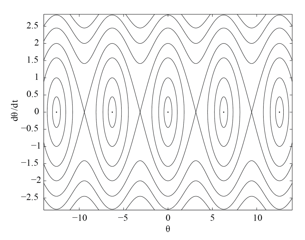
Our goal will be to describe the solutions of (3.8) in the phase plane [latex](\theta, d\theta/d\tau)[/latex]. Each initial condition [latex](\theta_0,t_0 \Omega_0)[/latex] will be associated with a curve in this plane. [1] If we know the arrangement of these solution curves, we can give a complete qualitative description of the dynamics of the nonlinear pendulum. An expression for the solution curves can be obtained as follows. If we multiply Equation (3.8) by [latex]d \theta / d \tau[/latex] and integrate, we obtain
[latex]\displaystyle \frac{1}{2} \left(\frac{d \theta}{d \tau}\right)^2 = \cos(\theta) + E,[/latex]
where the constant [latex]E[/latex] is arbitrary. It represents the energy of the dimensionless pendulum, and is conserved by the dynamics. The set of solution curves is thus described by
[latex]\displaystyle \frac{d \theta}{d \tau} = \pm \sqrt{2 \cos(\theta) + 2 E}, \qquad \displaystyle \frac{d \theta}{d t} \in \mathbb{R}, \qquad E \in [-1,\infty). \qquad (3.13)[/latex]
If [latex]E \gt 1[/latex], then the left hand side of Equation (3.13) is real for all values of [latex]\theta[/latex], and the corresponding solution curves are not closed. On the other hand, if [latex]-1 \le E \le 1[/latex], [latex]d \theta / dt[/latex] is real only for values of [latex]\theta[/latex] in intervals of the form [latex][-\arccos(E)+ 2 m \pi, \arccos(E) + 2 m \pi][/latex], [latex]m \in \mathbb{Z}[/latex], and the corresponding solution curves are closed orbits. Finally, because of the [latex]\pm[/latex] sign in the right hand side of (3.13), trajectories are symmetric with respect to the horizontal axis of the phase plane. We can use software such as Maple or MATLAB to plot these curves, paying particular attention to the special cases [latex]E = -1[/latex] and [latex]E = 1.[/latex] Figure 3.2 shows some of these trajectories. The description of the dynamics is completed by adding arrows to the curves, indicating the direction in which each trajectory is followed. This is not a difficult task since by definition [latex]d \theta / d \tau[/latex] is positive if [latex]\theta[/latex] increases as a function of [latex]\tau[/latex] and negative otherwise. As a consequence, the arrows point to the right in the upper part of the phase plane, and to the left in the lower part.
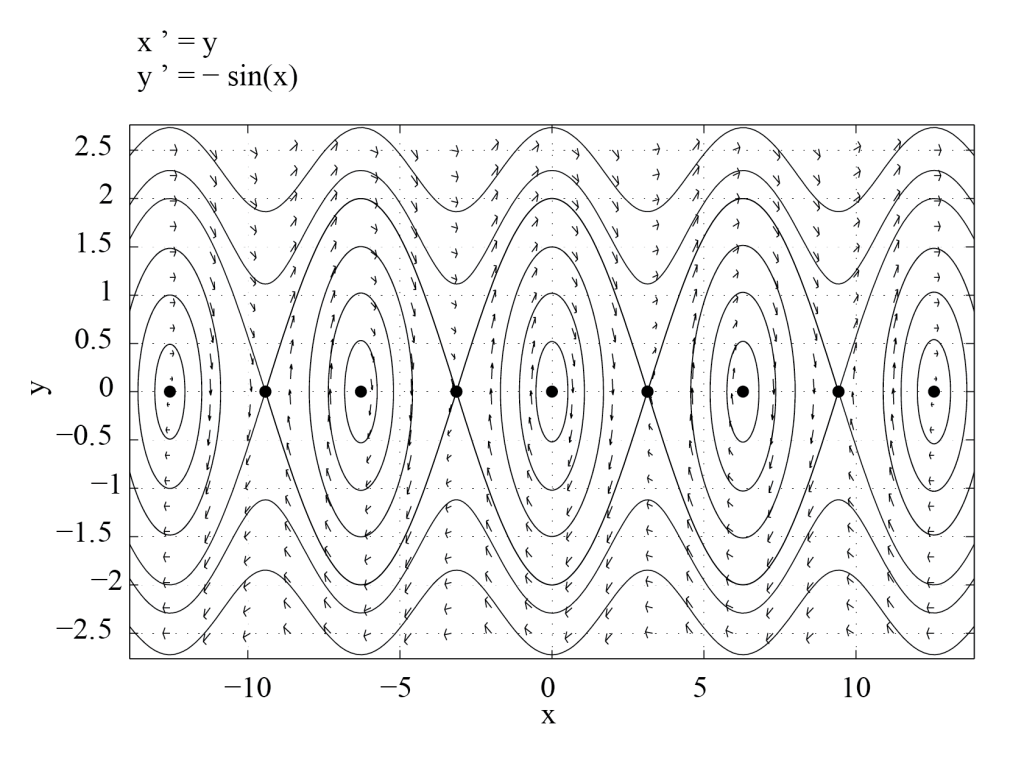
These results can be confirmed by using a phase plane analysis software such as the Phase Plane App. This program can be run in MATLAB. It allows the user to enter Equation (3.8) written as a first order system,
[latex]\displaystyle \frac{d \theta}{d \tau} = \Lambda, \qquad \frac{d \Lambda}{d \tau} = - \sin(\theta),[/latex]
and to plot the corresponding direction field and trajectories in the phase plane. The direction field for this system is obtained by plotting vectors with components [latex](1,-\sin(\theta))[/latex] (i.e. the right-hand-sides of the above equations) at points of coordinates [latex](\theta, \Lambda)[/latex] in the phase plane. The solution curve of (3.8) that goes through the point [latex](\theta, \Lambda)[/latex] is tangent to the direction field at that point. Figure 3.3 shows the phase plane for Equation (3.8), as obtained with PPLANE (developed by John C. Polking at Rice University). The solution curves found numerically are, as expected, in excellent agreement with those shown in Figure 3.2, which were obtained from Equation (3.13).
More generally, any dynamical system of the form
[latex]\displaystyle \frac{d^2 x}{d t^2} + \frac{d V}{d x} = 0 \quad (3.14)[/latex]
can be analyzed in this manner. Indeed, multiplying Equation (3.14) by [latex]dx/dt[/latex] and integrating once gives
[latex]\displaystyle \frac{1}{2} \left(\frac{d x}{d t}\right)^2 + V(x) = E, \quad (3.15)[/latex]
where the energy [latex]E[/latex] is a constant of motion. By letting [latex]\displaystyle \frac{d x}{d t} = \Lambda,[/latex] we obtain an equation for the solution curves in the ([latex]x[/latex],[latex]\Lambda[/latex]) plane:
[latex]\Lambda = \pm \sqrt{2 \left(E - V(x)\right)}, \qquad \Lambda \in \mathbb{R}.[/latex]
The corresponding phase portrait can be sketched by noticing that solution curves of energy [latex]E[/latex] only exist for values of [latex]x[/latex] such that [latex]E \ge V(x)[/latex]. In particular, fixed points of the dynamics, which are such that [latex]x(t) = x_0[/latex] is constant in time, are extrema of [latex]V(x)[/latex] (from Equation (3.14)), and the corresponding energy is given by [latex]E = V(x_0)[/latex] (from Equation (3.15)). One can check that minima of [latex]V[/latex] correspond to centers and maxima of [latex]V[/latex] to saddle points (see exercises). Moreover, trajectories of energy [latex]E[/latex] that cross the horizontal axis [latex](\Lambda = 0)[/latex] do so at values of [latex]x[/latex] such that [latex]V(x) = E[/latex]. These trajectories have a vertical tangent at the points of crossing (see exercises). Finally, trajectories which emanate from or converge to saddle points are tangent to the eigenvectors of the linearization of (3.14) written as a first order system, at these equilibrium points (see exercises). Figure 3.4 illustrates how the previous statements may be used to plot the phase portrait of Equation (3.14) with [latex]V(x) = - \cos(x)[/latex]. The result should be compared to Figures 3.2 and 3.3.
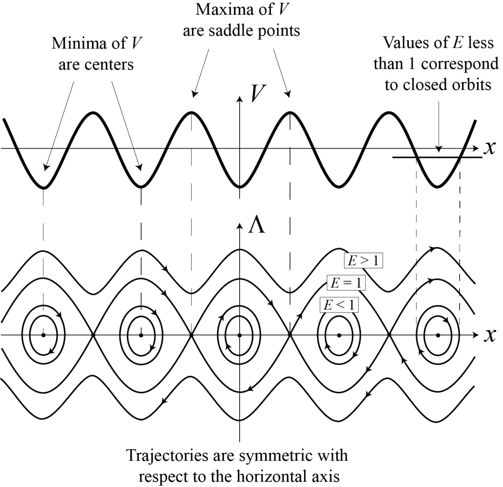
In Figure 3.4, the graph of [latex]V[/latex] as a function of [latex]x[/latex] is shown at the top. For each value of the energy [latex]E,[/latex] the quantity [latex]E - V[/latex] is proportional to [latex]\Lambda^2.[/latex] This information allows us to infer the behavior of the various solution curves in the [latex](x, \Lambda)[/latex] plane. The resulting phase portrait is plotted at the bottom.
Analysis in the presence of friction
In the presence of friction, the equation of motion for the nonlinear pendulum reads
[latex]\displaystyle \frac{d^2 \theta}{d t^2} = -\frac{g}{l} \sin(\theta) - \frac{c}{m} \frac{d \theta}{d t}. \qquad (3.16)[/latex]
As before, we first need to check that the dimension of the last term is the correct one. We have
[latex]\displaystyle \left[ \frac{c}{m} \frac{d \theta}{d t}\right] = \left[ \frac{1}{l \, m}\, c\, l\, \frac{d \theta}{d t}\right] = L^{-1} M^{-1} [\hbox{force}] = L^{-1} M^{-1} M L T^{-2} = T^{-2},[/latex]
where we have used the fact that
[latex]\displaystyle \vec F_f = -c\, l\, \frac{d\theta}{d t}\, \vec \theta.[/latex]
We now proceed to simplify Equation (3.16) by making the change of variable [latex]\tau = t / t_0[/latex]. We find
[latex]\displaystyle \frac{d^2 \theta}{d \tau^2} = - \sin(\theta) - \alpha \frac{d \theta}{d \tau}, \qquad \alpha = \frac{c}{m} \sqrt \frac{l}{g}, \qquad (3.17)[/latex]
and we can check that the parameter [latex]\alpha[/latex] is dimensionless, since
[latex][\alpha] = [c] M^{-1} T = [\hbox{force}] L^{-1} T M^{-1}\, T = M L T^{-2} \, L^{-1}\, T^2\, M^{-1} = 1.[/latex]
If [latex]c = 0[/latex], then [latex]\alpha = 0[/latex], and we recover Equation (3.8). The initial conditions for Equation (3.17) are, as before, given by Equation (3.9). Our next step in this analysis is to describe the phase portrait of Equation (3.17). We cannot use the same method as before, since the energy [latex]E[/latex] is no longer conserved. Indeed, we can calculate
[latex]\displaystyle \begin{align} \frac{d E}{d \tau} &= \frac{d}{d \tau} \left(\frac{1}{2} \left(\frac{d \theta}{d \tau}\right)^2 - \cos(\theta)\right) = \frac{d \theta}{d \tau} \, \frac{d^2 \theta}{d \tau^2} + \sin(\theta)\, \frac{d \theta}{d \tau} \\ &= \left(\frac{d^2 \theta}{d \tau^2} + \sin(\theta)\right) \frac{d \theta}{d \tau} \end{align}[/latex]
which gives
[latex]\displaystyle \frac{d E}{d \tau} = - \alpha \left(\frac{d \theta}{d \tau}\right)^2.[/latex]
Thus, since [latex]\alpha \gt 0[/latex], the energy [latex]E[/latex] is either constant (if [latex]d \theta / d \tau = 0[/latex]) or decreasing as a function of time. Since [latex]E[/latex] is bounded from below by [latex]-1[/latex], one can expect that trajectories for which [latex]d \theta / d \tau \ne 0[/latex] will converge towards solutions of energy [latex]E = -1[/latex]. Such solutions are given by [latex]\cos(\theta)=1[/latex], i.e. [latex]\theta = 2 n \pi[/latex], [latex]n \in \mathbb{Z}[/latex]; they are fixed points of the dynamics. Pictorially, we can imagine a particle being trapped in one of the valleys of the potential [latex]V(x)=-\cos(x)[/latex], losing energy as it moves, and therefore converging to the local minimum of the potential.
We now turn to the description of the phase plane for Equation (3.17). The corresponding first order system reads
[latex]\begin{align} \displaystyle \frac{d \theta}{d \tau} & = \Lambda, \\ \frac{d \Lambda}{d \tau} &= -\sin(\theta) - \alpha \Lambda. \end{align} \qquad (3.18)[/latex]
Fixed points are obtained by setting the left-hand-sides of the above equations to zero, that is solving [latex]\Lambda = 0[/latex] and [latex]\sin(\theta) = 0,[/latex] which corresponds to points of coordinates [latex](n \pi, 0)[/latex], [latex]n \in \mathbb{Z}[/latex] in the [latex](\theta,\Lambda)[/latex] plane. Information on the local dynamics may be obtained by linearizing system (3.18) about these fixed points. To this end, we set
[latex]\theta = n \pi + \mu, \qquad \Lambda = 0 + \nu,[/latex]
where [latex]\mu[/latex] and [latex]\nu[/latex] are small, and substitute in Equations (3.18). We find
[latex]\begin{align} \displaystyle \frac{d \mu}{d \tau} & = \nu, \\ \frac{d \nu}{d \tau} & = -\sin(n \pi + \mu) - \alpha \nu \qquad \qquad \qquad (3.19) \\ & = -\cos(n \pi) \mu - \alpha \nu + O(\mu^3), \end{align}[/latex]
which, if [latex]\mu[/latex] is small, can be approximated by the following linear system
[latex]\displaystyle \frac{d}{d \tau} \left(\begin{array}{c}\mu \cr \nu \end{array}\right) = \left( \begin{array}{cc} 0 & 1 \cr -\cos(n \pi) & - \alpha \end{array}\right) \left(\begin{array}{c}\mu \cr \nu \end{array}\right).[/latex]
The matrix
[latex]\displaystyle J(n \pi,0) = \left( \begin{array}{cc} 0 & 1 \cr -\cos(n \pi) & - \alpha \end{array}\right)[/latex]
is called the Jacobian of system (3.18) at the fixed point [latex](n \pi,0)[/latex]. The general solution of (3.19) can be written in terms of the eigenvalues and eigenvectors of [latex]J(n \pi,0)[/latex], and this information may be used to assess the linear stability of the corresponding fixed point [2]. Since the characteristic polynomial of a [latex]2 \times 2[/latex] matrix [latex]A[/latex] is given by [latex]\lambda^2 - \lambda \hbox{Tr}(A) + \det(A) = 0[/latex], the eigenvalues of [latex]J(n \pi, 0)[/latex] satisfy the characteristic equation
[latex]\displaystyle \lambda^2 + \alpha \lambda + \cos(n \pi) = 0.[/latex]
If [latex]n = 2 p[/latex] is even, [latex]\cos(n \pi) = 1[/latex]; the product of the two eigenvalues of [latex]J(2 p \pi, 0)[/latex] or, equivalently, the determinant of [latex]J(2 p \pi, 0)[/latex], is positive. The eigenvalues of [latex]J(2 p \pi, 0)[/latex] are thus either of the same sign and real, or complex conjugate (recall that the eigenvalues of a matrix with real entries either are real or come in complex conjugate pairs). The sum of the eigenvalues of [latex]J(2 p \pi, 0)[/latex] or, equivalently, the trace of [latex]J(2 p \pi, 0)[/latex], is [latex]-\alpha[/latex], which is negative. The fixed points [latex](2 p \pi,0)[/latex], [latex]p \in \mathbb{Z}[/latex], are thus always stable. We can decide on the nature of these fixed points by comparing the square of the trace of [latex]J(2 p \pi, 0)[/latex] to four times its determinant or, more directly, by calculating the eigenvalues of [latex]J(2 p \pi, 0)[/latex]. They are given by
[latex]\displaystyle \lambda^\pm_{(2 p \pi,0)} = -\frac{\alpha}{2} \pm \sqrt{\frac{\alpha^2}{4}-1}.[/latex]
The fixed points [latex](2 p \pi,0)[/latex] are therefore stable nodes (if [latex]\alpha^2 \gt 4)[/latex] or stable spirals (if [latex]\alpha^2 \lt 4[/latex]). Similarly, if [latex]n = 2 p + 1[/latex] is odd, the eigenvalues of [latex]J((2 p + 1)\pi,0)[/latex] have a product equal to [latex]\cos((2 p + 1) \pi) = -1[/latex] and are therefore both real and of opposite signs. [3] As a consequence, the fixed points [latex]((2 p + 1)\pi,0)[/latex] are saddle points. For completeness, we give the eigenvalues of [latex]J((2 p + 1)\pi,0)[/latex], which read
[latex]\displaystyle \lambda^\pm_{((2 p + 1)\pi,0)} = - \frac{\alpha}{2} \pm \sqrt{\frac{\alpha^2}{4} + 1}.[/latex]
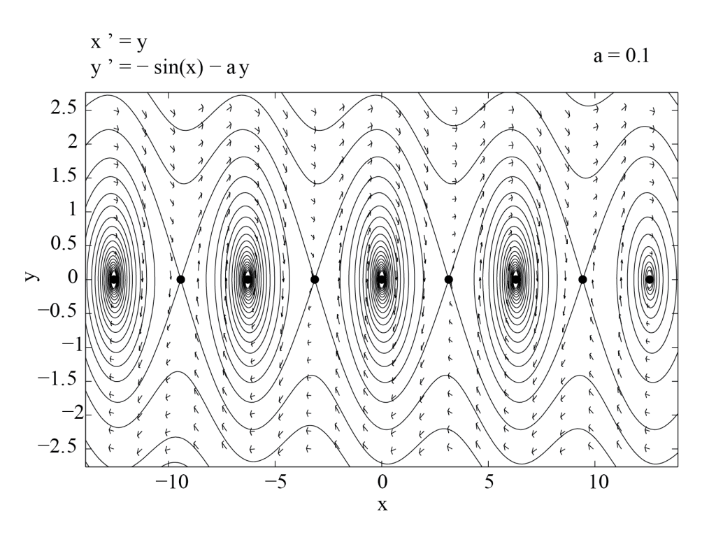
These facts are summarized in the phase portrait of Figure 3.5, obtained with PPLANE. We see that trajectories tangent to the eigenvectors of [latex]J((2 p + 1) \pi, 0)[/latex] at the points [latex]((2 p + 1) \pi, 0)[/latex] are separatrices of the phase plane. They are called the stable and unstable manifolds of the saddle points [latex]((2 p + 1) \pi,0)[/latex]. As expected, the unstable manifold of [latex]((2 p + 1) \pi,0)[/latex] contains the the stable fixed points [latex](2 p \pi,0)[/latex] and [latex]((2 p + 2) \pi,0)[/latex]. Trajectories which connect two different fixed points are called heteroclinic orbits.
Summary
The nonlinear pendulum provides a good illustration of the modeling process. Newton's law, together with a set of simplifying hypotheses, allowed us to derive a differential equation model for the angle of the nonlinear pendulum, with or without friction. We then reviewed how to use dimensional analysis to rescale dependent and independent variables in order to obtain a dimensionless model with a reduced number of parameters. The second order differential equations derived in this chapter were studied in terms of phase plane analysis. The phase plane of a two-dimensional conservative system may be obtained by plotting level-sets of the conserved energy. Curves of constant energy may either be found analytically or drawn from the graph of the potential energy. The phase plane of non-conservative two-dimensional dynamical systems may often be inferred from the analysis of the fixed points of the system and of their linear stability. More precisely, nonlinear terms do not change the nature of stable or unstable nodes and spirals, and of saddles points. The reader may want to consult an elementary text on dynamical systems for further details.
Food for Thought
Problem 1
Show that
[latex]\theta(\tau) = C \cos(\tau + \phi),[/latex] with [latex]A, B \in \mathbb{R}[/latex]
can be written as
[latex]\theta(\tau) = A \cos(\tau) + B \sin(\tau),[/latex]
with [latex]C, \phi \in \mathbb{R}[/latex] by expressing [latex]A[/latex] and [latex]B[/latex] in terms of [latex]C[/latex] and [latex]\phi[/latex].
Conversely, explain how you would find [latex]C[/latex] and [latex]\phi[/latex], knowing [latex]A[/latex] and [latex]B[/latex]. Are [latex]C[/latex] and [latex]\phi[/latex] uniquely determined? Why or why not?
Problem 2
It is shown in the text that there exist solutions to Equation (3.8) which exhibit periodic oscillations.
- Write down an equation for the period [latex]T[/latex] of these oscillations, as an integral over the angle variable [latex]\theta[/latex]. Your answer should depend on the energy [latex]E[/latex].
- Show that the period [latex]T[/latex] is an increasing function of the energy [latex]E[/latex]. In other words, show that the period of the nonlinear pendulum increases with its amplitude.
Problem 3
Consider a one-dimensional frictionless spring-mass system, where the forces acting on the mass [latex]m[/latex] at position [latex]x[/latex] are the force of gravity [latex]F_g = - m g[/latex] with [latex]g \gt 0[/latex] constant, and the restoring force of the spring given by [latex]F_r = - k (x - x_0)[/latex], where [latex]k \gt 0[/latex] and [latex]x_0[/latex] are constant.
- Use Newton's law to write down an equation for the position [latex]x[/latex] of the mass.
- Re-scale the resulting equation. How many parameters can you get rid of?
- Show that the frictionless spring-mass system is conservative.
- Describe the dynamics of this system.
Problem 4
Consider the following system of differential equations,
[latex]\frac{d x}{d t} = F(x,y) \qquad \frac{d y}{d t} = G(x,y).[/latex]
- What conditions should be satisfied by the coordinates [latex]x[/latex] and [latex]y[/latex] of a fixed point of this system?
- Assume that [latex](x_0, y_0)[/latex] is a fixed point of the above system. We are interested in describing the dynamics of the system in the vicinity of the fixed point. To do so, set [latex]x = x_0 + \mu[/latex], [latex]y = y_0 + \nu[/latex], substitute these expressions into the above system, and Taylor-expand the right-hand sides in powers of [latex]\mu[/latex] and [latex]\nu[/latex], up to order two.
- Using the results of part (2) above, show that the linearization of the system about the fixed point [latex](x_0,y_0)[/latex] reads
[latex]\displaystyle \frac{d}{d t} \left(\begin{array}{c}\mu \cr \nu \end{array}\right) = J(x_0,y_0) \left(\begin{array}{c}\mu \cr \nu \end{array}\right),[/latex]
where the Jacobian [latex]J(x_0,y_0)[/latex] of the system at [latex](x_0,y_0)[/latex] is given by
[latex]\displaystyle J(x_0,y_0) = \left(\begin{array}{cc} \left. \frac{\partial F(x,y)}{\partial x} \right|_{(x_0,y_0)} & \left. \frac{\partial F(x,y)}{\partial y} \right|_{(x_0,y_0)} \cr \left. \frac{\partial G(x,y)}{\partial x} \right|_{(x_0,y_0)} & \left. \frac{\partial G(x,y)}{\partial y} \right|_{(x_0,y_0)}\end{array}\right).[/latex]
Problem 5
Consider a linear system of the form
[latex]\displaystyle \frac{d}{d t} \left(\begin{array}{c} x \cr y \end{array}\right) = \left( \begin{array}{cc} a & 0 \cr 0 & b \end{array} \right) \left(\begin{array}{c} x \cr y \end{array}\right),[/latex]
where [latex]a \gt 0,\ b \lt 0.[/latex]
- Give the general solution to this system.
- Sketch the phase plane of this system, paying particular attention to special trajectories. Can you tell in which direction the solution curves are traced out as time goes on? If so, add arrows to the trajectories you drew.
Problem 6
Sketch the phase plane in the vicinity of the following types of fixed points:
- A stable node.
- An unstable spiral.
- A center.
- A saddle point.
Problem 7
Describe the eigenvalues of the linearization of a system of dimension two in the vicinity of the following fixed points:
- A stable node.
- An unstable spiral.
- A center.
- A saddle point.
Problem 8
Find a 2 by 2 matrix [latex]A[/latex] whose entries are all non-zero, and such that the linear system [latex]\dot X = A X[/latex] has a fixed point of the following type at the origin:
- A stable node.
- An unstable spiral.
- A center.
- A saddle point.
Check your answer with a phase plane analysis software, such as the Phase Plane App or equivalent software.
Problem 9
Explain how you would determine the nature (e.g. stable or unstable node or spiral, linear center or saddle point) of a fixed point [latex](x_0,y_0)[/latex] of the two-dimensional differential system
[latex]\displaystyle \frac{d x}{d t} = F(x,y), \qquad \frac{d y}{d t} = G(x,y).[/latex]
Problem 10
Sketch the phase planes of the following dynamical systems. If the answer depends on the parameter(s) of the problem, all cases should be considered. Use the Phase Plane App or equivalent software to check your results.
- [latex]\displaystyle \frac{d}{d t} \left(\begin{array}{c}x \cr y \end{array}\right) = \left(\begin{array}{c}y \cr - x - c\, y \end{array}\right), \qquad c \gt 0[/latex].
- [latex]\displaystyle \frac{d}{d t} \left(\begin{array}{c}x \cr y \end{array}\right) = \left(\begin{array}{c}y \cr x (x+1) (x-2) \end{array}\right)[/latex].
- [latex]\displaystyle \frac{d}{d t} \left(\begin{array}{c}x \cr y \end{array}\right) = \left(\begin{array}{c}y \cr x (x+1) (x-2) - c\, y \end{array}\right), \qquad c \gt 0[/latex].
- [latex]\displaystyle \frac{d}{d t} \left(\begin{array}{c}x \cr y \end{array}\right) = \left(\begin{array}{c} x (6 - 2 y) \cr y (x - 3) \end{array}\right)[/latex].
- [latex]\displaystyle \frac{d}{d t} \left(\begin{array}{c}x \cr y \end{array}\right) = \left(\begin{array}{c} x (1 - x - 2 y) \cr y (1 - 3 x - y) / 2 \end{array}\right)[/latex].
- [latex]\displaystyle \frac{d}{d t} \left(\begin{array}{c}x \cr y \end{array}\right) = \left(\begin{array}{c} y \cr x -x^3 \end{array}\right)[/latex].
Problem 11
Consider the van der Pol oscillator,
[latex]\displaystyle \frac{d^2 x}{d t^2} + \omega^2 x = \epsilon \frac{d x}{d t} (1 - x^2), \qquad \epsilon \ge 0.[/latex]
- Describe the dynamics when [latex]\epsilon=0[/latex].
- What is the effect of the right-hand-side when [latex]|x|[/latex] is small?
- What is the effect of the right-hand-side when [latex]|x|[/latex] is much larger than [latex]1[/latex]?
- Based on your answers to the previous questions, explain what you expect to happen for intermediate values of [latex]|x|[/latex].
- Sketch the phase plane of the van der Pol oscillator.
- Check your answer with the Phase Plane App or equivalent software. Is the result surprising? Why or why not?
Problem 12
Consider the following differential equation, [latex]\displaystyle \frac{d x}{d t} = \lambda x - \gamma x^3.[/latex]
- What is the dimension of [latex]\lambda[/latex]?
- What is the dimension of [latex]\gamma[/latex]? Your answer should be in terms of the dimension of [latex]x[/latex], denoted by [latex][x][/latex].
- Let [latex]t_0[/latex] be a characteristic time scale for this problem. Define a dimensionless time variable [latex]\tau = t / t_0[/latex], and show that you can make a change of variable from [latex]t[/latex] to [latex]\tau[/latex], to "remove" the parameter [latex]\lambda[/latex].
- Can you find a change of variable that would allow you to remove [latex]\gamma[/latex] as well?
Problem 13
The force of gravity between two bodies of mass [latex]m_1[/latex] and [latex]m_2[/latex] has intensity [latex]\displaystyle F = G \frac{m_1 m_2}{r^2},[/latex] where [latex]r[/latex] is the distance between the centers of mass of the two bodies, and [latex]G[/latex] is the gravitational constant.
- Use this formula to show that for an object of mass [latex]m[/latex] at the surface of the Earth, one can approximate the force [latex]F[/latex] by [latex]F \simeq m g[/latex], where the acceleration of gravity [latex]g[/latex] is constant.
- Express [latex]g[/latex] in terms of [latex]G[/latex], the mass [latex]M[/latex] of the Earth, and the radius [latex]R[/latex] of the Earth.
Problem 14
Consider a smooth function [latex]f(x)[/latex], and its Taylor expansion near [latex]x = x_0[/latex],
[latex]\displaystyle f(x) = \sum_{i = 0}^n f^{(i)}(x_0) \frac{(x - x_0)^i}{i !} + f^{(n+1)}(\bar x) \frac{(x - x_0)^{n+1}}{(n+1)!}, \qquad (3.20)[/latex]
where [latex]\bar x \in [x_0,x][/latex]. Let [latex]E_n(x)[/latex] be the error made by approximating [latex]f[/latex] with its Taylor expansion truncated to order [latex]n[/latex],
[latex]\displaystyle E_n(x) = f(x) - \sum_{i = 0}^n f^{(i)}(x_0) \frac{(x - x_0)^i}{i !} .[/latex]
- Use Equation (3.20) above to write the Taylor expansion of [latex]f(x) = \cos(x)[/latex], near [latex]x_0 = 0[/latex] to order [latex]n = 5[/latex].
- Find a condition on [latex]|x|[/latex] which ensures that [latex]\vert E_5(x) \vert \lt 0.05[/latex].
- Use a calculator or MATLAB to check your answer to the previous question.
Problem 15
Consider the following model
[latex]\displaystyle \frac{\partial u}{\partial t} = \mu u + \alpha \frac{\partial^2 u}{\partial x^2} - \beta u^3, \qquad u \in \mathbb{R}, \quad \alpha, \beta \gt 0.[/latex]
- What are the dimensions of the parameters [latex]\alpha[/latex], [latex]\beta[/latex] and [latex]\mu[/latex]? Write [latex][u][/latex] for the dimension of [latex]u[/latex].
- How many relevant parameters does this model have? Explain.
Problem 16
Consider the second order differential equation [latex]\displaystyle \frac{d^2 x}{d t^2} + \frac{d V}{d x} = 0,[/latex] where [latex]V(x)[/latex] is a smooth potential.
- Re-write this second order equation as a first-order system.
- Find the fixed points of the first-order system and show that they correspond to critical points of [latex]V[/latex].
- Find the linearized system about an arbitrary fixed point and show that maxima of [latex]V[/latex] correspond to saddle points and minima of [latex]V[/latex] to linear centers.
Problem 17
Consider the dynamical system [latex]\displaystyle \frac{d^2 x}{d t^2} + \frac{d V}{d x} = 0,[/latex] where [latex]V(x)[/latex] is a smooth function. Assume that [latex](x_0, 0)[/latex] is a saddle point of the corresponding first-order system of differential equations.
Find an equation describing the trajectories in the associated phase plane near the fixed point [latex](x_0, 0)[/latex].
Problem 18
Consider the dynamical system [latex]\displaystyle \frac{d^2 x}{d t^2} + \frac{d V}{d x} = 0,[/latex] where [latex]V(x)[/latex] is a smooth function.
Show that, in the phase plane of coordinates [latex]\left(x,\dfrac{dx}{dt}\right)[/latex], trajectories with energy [latex]E[/latex] such that [latex]\min(V) \lt E \lt \max(V)[/latex] (where [latex]\min(V)[/latex] and/or [latex]\max(V)[/latex] may be infinite depending on the potential [latex]V[/latex]) cross the [latex]x[/latex]-axis. In addition, show that they have a vertical tangent at points of crossing where [latex]\displaystyle \frac{d V}{d x} \ne 0[/latex].
Problem 19
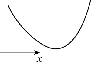
Sketch the phase plane associated with the differential equation [latex]\displaystyle \frac{d^2 x}{d t^2} + \frac{d V}{d x}=0,[/latex] where the potential [latex]V(x)[/latex] has the shape given below. Only the portion of the graph of [latex]V(x)[/latex] near its minimum is shown. You may assume that the trends suggested by the picture continue outside of the plot area, i.e. that [latex]\displaystyle \lim_{x \to - \infty} V(x) = \lim_{x \to + \infty} V(x) = + \infty.[/latex]
Problem 20
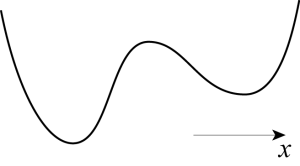
Sketch the phase plane associated with the differential equation [latex]\displaystyle \frac{d^2 x}{d t^2} + \frac{d V}{d x} = 0,[/latex] where the potential [latex]V(x)[/latex] has the shape given below. Only the portion of the graph of [latex]V(x)[/latex] near its extrema is shown. You may assume that the trends suggested by the picture continue outside of the plot area, i.e. that [latex]\displaystyle \lim_{x \to - \infty} V(x) = \lim_{x \to + \infty} V(x) = + \infty.[/latex]
Problem 21
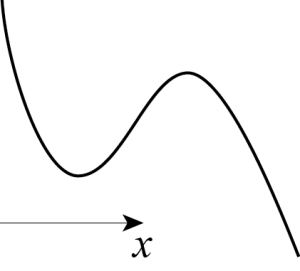
Sketch the phase plane associated with the differential equation [latex]\displaystyle \frac{d^2 x}{d t^2} + \frac{d V}{d x} = 0,[/latex] where the potential [latex]V(x)[/latex] has the shape given below. Only the portion of the graph of [latex]V(x)[/latex] near its extrema is shown. You may assume that the trends suggested by the picture continue outside of the plot area, i.e. that [latex]\displaystyle \lim_{x \to - \infty} V(x) = + \infty, \quad \lim_{x \to + \infty} V(x) = \,- \infty.[/latex]
Problem 22
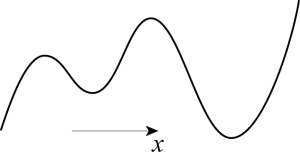
Sketch the phase plane associated with the differential equation [latex]\displaystyle \frac{d^2 x}{d t^2} + \frac{d V}{d x} = 0,[/latex] where the potential [latex]V(x)[/latex] has the shape given below. Only the portion of the graph of [latex]V(x)[/latex] near its extrema is shown. You may assume that the trends suggested by the picture continue outside of the plot area, i.e. that [latex]\displaystyle \lim_{x \to - \infty} V(x) = \,- \infty, \quad \lim_{x \to + \infty} V(x) = + \infty.[/latex]
Problem 23
Consider the Navier-Stokes equation
[latex]\displaystyle \frac{\partial \vec v}{\partial t} + \left(\vec v \cdot \nabla \right) \vec v = -\frac{1}{\rho} \nabla p + \nu \nabla^2 \vec v +\frac{1}{\rho} \vec F,[/latex]
where the vector [latex]\vec v[/latex] represents the velocity of a fluid in 3 spatial dimensions, [latex]\rho[/latex] is the density of the fluid, [latex]p[/latex] is its pressure, [latex]\nu[/latex] is the kinematic viscosity of the fluid, and [latex]\vec F[/latex] stands for the density of bulk forces applied to the fluid. The operator [latex]\nabla[/latex] is the gradient in 3 dimensions.
-
What is the dimension of the two terms on the left hand side of the equation? Why should these dimensions be the same?
-
Use this information to find the dimension of [latex]p[/latex] and that of [latex]\vec F[/latex]. Is the result what you expected, based on your knowledge of forces and pressure?
-
Find the dimension of [latex]\nu[/latex].
-
Let [latex]U[/latex] be a characteristic velocity, and [latex]l[/latex] a characteristic length. Define dimensionless variables [latex]\vec V[/latex] and [latex]\vec X[/latex] such that [latex]\vec v = U \vec V[/latex] and [latex]\vec x = l \vec X[/latex], where [latex]\vec x[/latex] is the position vector. Re-write the Navier-Stokes equation in terms of these new variables.
-
Show that if you now re-scale time and introduce dimensionless versions of [latex]p[/latex] and [latex]\vec F[/latex], then the dimensionless Navier-Stokes equation involves only one parameter, [latex]Re = U l / \nu[/latex]. This parameter is called the Reynolds number.
- See the appendix on ordinary differential equations for the existence and uniqueness of solutions to initial value problems, and for a brief description of phase plane analysis. ↵
- See the phase plane analysis section of the appendix on ordinary differential equations for a review. ↵
- Since [latex]J(n \pi, 0)[/latex] has real entries, if its eigenvalues were complex, then they would be complex conjugate and their product would have to be positive. ↵

